·Table of Contents
·Methods and Instrumentation
Procedures of Ultrasonic Testing Based on Digital Techniques
W. Michnowski J. MierzwaZaklad Badan Materialow ULTRA Wrocaw, www.ultrasonic.home.pl
e-mail: ultrasonic@home.pl
Contact
 ·Table of Contents ·Methods and Instrumentation |
Procedures of Ultrasonic Testing Based on Digital TechniquesW. Michnowski J. MierzwaZaklad Badan Materialow ULTRA Wrocaw, www.ultrasonic.home.pl e-mail: ultrasonic@home.pl Contact |
In not very long history of ultrasonic tests normative acts, technical conditions and the directives of these surveys were established, we can say that they create quite big library, which is still growing. Some of these acts are quite complicated, and adapting them may be arduous, so it leads to interpretative differences, or even test's failures. Essential cause of difficulties with proper application of these acts is often their high degree of complication and very low clearance. The reason is that at the time, when these acts were established, only analog or hybrid defectoscopes existed, and these acts are adapted to small potential of these defectoscope. Application of digital defectoscopes, the ones which are controlled by computer, enables including research procedures based on existing normative acts. Application of defectoscope including these programs- procedures facilitates a lot ultrasonic tests and make them completely reproducible. We can divide the surveys procedures into two groups:
I - UNIVERSAL PROCEDURES
Universal procedures are used in
tests of very different objects. Examples of these procedures are, for
example, equivalent size of failure estimate procedure (AVG - DGS)
strengthening range regulation procedure, time base automation, probes and
materials catalogues and so on. Some of the universal procedures are used in
object procedures as their part. Examples of universal procedures are given in
chapter 2.
II - OBJECT PROCEDURES
Object procedures usually give
complete ways of testing definite objects e.g. Welding testing according to
definite standard, axle set testing, rail testing, high voltage insulator
testing, etc. Among commercially available digital defectoscopes not numerous
are equipped with richer set of universal procedures, but there is a complete
lack of defectoscopes equipped with object procedures. Results of research on
programming and implementation of some procedures in digital ultrasonic
defectoscopes are shown below.
To begin with digital defectoscope notion
is specified.
Even if defectoscope doesn't have one of the listed features, it is a hybrid defectoscope, if it doesn't have any of the listed features it is an analog defectoscope. According to this partition a really lot of contemporary constructions are hybrid defectoscopes, however analog defectoscopes are used very oftenEven if defectoscope doesn't have one of the listed features, it is a hybrid defectoscope, if it doesn't have any of the listed features it is an analog defectoscope.
According to this partition a really lot of contemporary constructions are hybrid defectoscopes, however analog defectoscopes are used very often
2.1 Estimate of equivalent size of failure according to AVG- DGS
diagrams
The way of estimate of equivalent size of failure
according to AVG- DGS diagrams elaborated already in the sixties in known
Krautkramer company is still base of ultrasonic tests and estimates and is
still included in many actually existing legal acts. This way is suitable
especially to be expressed in procedure which may be included in any digital
defectoscope, and this procedure may be fully automated and - for this- very
easy and fast in usage. Application of this procedure requires from
defectoscope to include catalogued data concerning used probes and their
parameters and acoustic parameters of possibly tested materials. Then the
defectoscope may automatically announce size of equivalent failure for each
chosen echo of the failure. In figure 1 detected failure with equivalent size
R=1,8 mm in distance 43,5 mm from the probe with angle beam 70 is in depth
15mm in this case it is a cylindrical hole which is 1,5 mm in diameter.
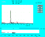
 Fig 1: Photo of defectoscope's screen in FD (flaw detector)
mod Fig 1: Photo of defectoscope's screen in FD (flaw detector)
mod |
 Fig 1: Fig 1: |
2.2. Testing of welding - scanner
The scanner elaborated
over ten years ago in ULTRA company is used for tests of welds and metal
sheets, and also for other purposes. This scanner make use of surface waves
for locating position of testing probe on tested surface. In figure (next to
the text) the scanner functioning scheme is shown. In this type of scanner
ultrasonic surface waves are used for check of place of testing probe
position. Ultrasonic surface wave transmitter probe 1 with magnetic holder
located at the beginning of the weld in parallel to it sends surface wave
impulse. Double probe 2 receives these signal by of two its converters.
The run time of these impulses is measure of distance of probes 1 and 2. The
second converter of testing probe is standard probe for welding testing e.g.
4T70o9x10C.Two probes distance measurement cycle and testing cycle
follow alternately, and measure distance and the result of testing are
information about given cut of the welding. Set of these information is
processed into failure maps, welding estimates etc.
Figure 2 shows screen of defectoscope working in SK- Scanner
mode.
Figure 3 shows screen of defectoscope working in DP-
Display, where sonogram and estimate of the welding is shown.
 Fig 2: Photo of the defectoscope screen working
in SK mode All the defectoscope settings and presentation and
registration of results in this mode of work are executed automatically.
The visible echo of failure with equivalent size R=2,4 mm in distance
Z=155,5 mm on the depth about 12mm. Lighter rectangle with the map of
detected failures drawn. Fig 2: Photo of the defectoscope screen working
in SK mode All the defectoscope settings and presentation and
registration of results in this mode of work are executed automatically.
The visible echo of failure with equivalent size R=2,4 mm in distance
Z=155,5 mm on the depth about 12mm. Lighter rectangle with the map of
detected failures drawn. |
 Fig 3: Defectoscope screen in DP mode Visible
map of detected failures on welding cut with estimate of the welding
executed automatically. Class U= 4 is a welding in class 4 according to
PN_ 89/M- 697770. Sensitivity of failure registration 1,2 mm of
equivalent failure. Fig 3: Defectoscope screen in DP mode Visible
map of detected failures on welding cut with estimate of the welding
executed automatically. Class U= 4 is a welding in class 4 according to
PN_ 89/M- 697770. Sensitivity of failure registration 1,2 mm of
equivalent failure. Key buttons Print activates automatic printout of finished reports. |
Written ultrasonic test procedures concern existing normative acts. It's obvious that these procedures have to be compatible with requirements of these acts , and it is often connected with resignation of some of already existing higher potentials of digital defectoscopes. The issue of the future is modification of normative acts for them to take into consideration increased digital defectoscope potentials e.g. to take into account in estimate of tested objects requirements connected with mechanics of the strokes.
Stage 1 Defectoscope scaling on comparative model.
The
task realized on this stage is inserting into computer memory the data
obtained on model made according to the standard. These data will be used
later, during the actual tests of axles. This stage consists of three
consecutive steps of proceeding. Each of the step of the scaling has a window,
appearing on the screen, with description and drawing of test geometry. The
purpose of scaling on this comparative model is to catalogue defectoscope
settings, e.g. observation ranges, probes number, strengthening etc; after
establishing them, they may be automatically used during axle tests. It's
enough to perform scaling on the model once, and registered results will be
automatically loaded and used on every step of the test. They may be used
repeatedly for tests of next axles.
Stage 2 axles test
The task realized in this stage is
actual test of axles according to the standard. This stage consists of eight
consecutive steps. After pressing the Start button, the computer demands to
announce data, e.g. axle number, and wheel set number and text concerning
current step of procedure is displayed. The end of procedure is registration
of the failure. As a registration we understand saving the defectoscope screen
in BMP format on which besides the commentary there are (automatically) number
of axle and wheel set number and test date and stage of strengthening. Second
element of registration is description of the failure, which appears
immediately after remembering the screen. The failures registered during
current measurement may be watched and edited. After execution of all the
steps the card with spaces to fill in appears. The spaces on this card are
automatically rewritten from previous measurement (to reduce to minimum
operator expenditure). Finishing testing causes listing data to tests register
and obviously they may be remembered.
 Fig 4: Screen during test with current procedure step
displayed Fig 4: Screen during test with current procedure step
displayed
|  Fig 7: TScreen with picture for current step of procedure
displayed Fig 7: TScreen with picture for current step of procedure
displayed |
| © AIPnD , created by NDT.net | |Home| |Top| |